Introduction
Have you ever wondered how a thermometer translates the temperature of a room into an easy-to-read number on a screen? This project takes that question head-on by building a digital thermometer using hardware components like an LM35 temperature sensor, an ADC MCP3201, and an FPGA. What makes this thermometer special is how everything is programmed and controlled using VHDL. The result? A real-time temperature monitoring system that is not just accurate but also efficient.
🚀 Project Overview
The Digital Thermometer is designed to read temperature data from an LM35 sensor, process the analog signal through an Analog-to-Digital Converter (ADC), and display the temperature in Celsius using a 7-segment display. The entire system is controlled by an FPGA programmed in VHDL.
🔧 Components Involved:
- LM35 Temperature Sensor: This sensor converts the room temperature into a corresponding analog voltage.
- MCP3201 ADC: The analog signal from the sensor is converted into a digital value through the ADC.
- FPGA (Field Programmable Gate Array): All the digital data processing happens here. The FPGA was programmed using VHDL, which manages everything from data conversion to real-time display output.
- 7-Segment Display: This display module shows the temperature in real-time with both the integer and decimal parts.
🔍 Detailed Breakdown
1. Sensor Integration:
The project starts by using the LM35 temperature sensor. This sensor outputs an analog voltage proportional to the temperature. For instance, a temperature of 26°C would result in an output voltage of 260 mV.
2. Analog-to-Digital Conversion:
The analog signal from the LM35 is then passed to the MCP3201 ADC, which converts it into a 12-bit digital value. This is where the FPGA takes over. The VHDL code I developed ensures proper communication between the ADC and the FPGA via SPI (Serial Peripheral Interface), ensuring the digital values are accurate and correspond correctly to the temperature readings.
3. Data Processing with VHDL:
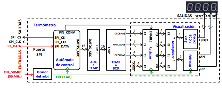
Inside the FPGA, I implemented various modules in VHDL to handle different parts of the data flow:
- Clock Divider: The ADC operates on a lower frequency, so I created a clock divider to reduce the 50MHz clock down to 1kHz.
- Temperature Conversion: The digital data from the ADC is processed, and I wrote logic to convert these digital values into readable Celsius units.
- 7-Segment Display Control: I programmed a BCD (Binary Coded Decimal) converter to display the temperature on the 7-segment display, handling both the integer and decimal parts. This ensures the temperature is displayed accurately and legibly in real-time.

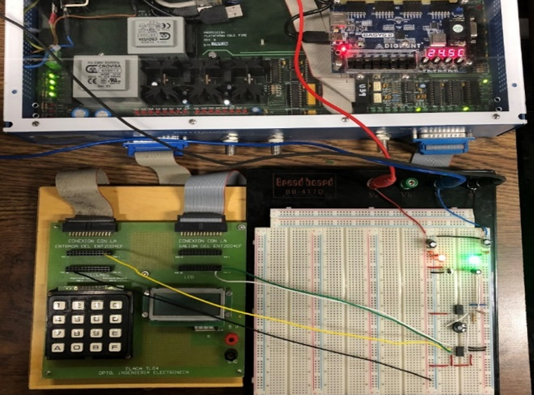
Circuit used for the digital thermometer project
4. Real-Time Display:
Once the temperature is processed, the result is displayed in real-time on a 7-segment display. The display shows both the integer and decimal parts of the temperature, ensuring precise monitoring at a glance. The refresh rate is synchronized with the clock divider, ensuring the display updates smoothly.
🛠️ Challenges Overcome
One of the biggest challenges was ensuring accurate data conversion between the ADC and FPGA. Programming the SPI communication between the MCP3201 and the FPGA required precise timing, which I achieved through the clock divider. Additionally, making sure that the temperature values displayed correctly on the 7-segment display involved writing efficient VHDL code to handle binary to BCD conversion.
💡 Why This Project Matters
This project highlights the importance of FPGA programming and hardware design in solving real-world problems. It’s more than just measuring temperature; it’s about mastering the process of transforming raw sensor data into meaningful digital output that can be used in various applications.
In an era where precision is key, projects like this show how effective design and thoughtful programming can convert simple environmental data into actionable insights.
